Here you will find out latest app notes.
A better IC model can improve PSpice simulation accuracies, but other components, such as, passive components, can influence simulation accuracy as much as IC models. This application note will cover various examples to describe the effects of frequency and temperature on the behavior of selected common passive components.
This section covers the effects of frequency on the behavior of the following selected models:
Resistor Models
A resistor that appears to work in straightforward manner can change its behavior with respect to the Operating frequency in a DC circuit. Depending upon its value and frequency of an operation, a resistor can behave in a resistive, capacitive, or inductive manner.
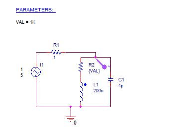
Figure 1: Resistor Model Circuit
In Figure 1, you can see that three major elements are associated with a standard 0.25-watt carbon or metal film resistor. With the first being the resistor itself, second and third are the two major parasitic elements that are included with every resistor. One is a parasitic capacitor formed across the resistor; this capacitor reduces the resistor's impedance at high frequency. Other is a parasitic lead inductance; this inductance increases the impedance as frequency increases.
A small resistor does not exhibit much shunt capacitance, but its impedance increases with frequency due to the series inductance. In case of large resistors, the capacitance reduces the impedance as frequency increases, whereas the inductance is negligible.
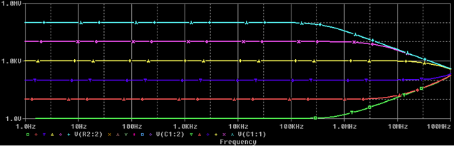
Figure 2: Impedance versus Frequency
Figure 2 shows a plot of impedance versus frequency for several resistor values. This plot clearly illustrates that a resistance value has a huge effect on resistor's behavior at higher frequencies.
Multilayer ceramic capacitors have much the same parasitic elements as a resistor, but are slightly rearranged. Figure 3 illustrates the behavior of a frequency-dependent model for a basic leaded ceramic capacitor, plotting impedance versus frequency for several typical part values. The equivalent series resistance (ESR) limits the Q of the capacitor; the parasitic inductance and capacitance value set the self-resonant frequency.
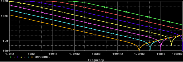
Figure 3: Ceramic Capacitor Model Behavior
All capacitors self-resonate at some frequency, after which the impedance starts to climb inductively.
Resistors and capacitors are only part of the problem in making accurate PSpice simulations. Conductors (PCB traces and wires) and inductors also deviate from ideal as the frequency increases.
A conductor that looks like a small resistor at DC has an increasing impedance with a frequency that is dependent on the physical dimensions of the conductor. Its inductance can be approximated by an inductor of about 20 nH per inch of length in series with the DC resistance. Thus, a conductor looks inductive at frequencies as low as 10 kHz up to the length that is about a quarter-wavelength long. At longer lengths, the conductor undergoes multiple pole and zero resonances like an antenna. The frequency where a conductor stops looking inductive and starts to act like an antenna can be found using the formula,
F=2850/L
where L is a quarter of the wavelength in inches, and F is in MHz. Thus, a conductor that is 10 inches long will behave like an antenna when the frequency is 285 MHz or greater. Most PCB traces are not long enough to act as antennas, but ribbon cables can be. On controlled impedance PCB's, the traces look like transmission lines.
Even power and ground planes used in a PCB design don't escape frequency effects. The impedance of a ground plane doesn't look inductive at higher frequencies; it looks lossy. At higher frequencies, the skin effect of the plane starts to dominate and increase the planes impedance. The skin effect is proportional to the square root of the frequency, so it doesn't rise as fast as does that of a wire that is behaving inductively.
Inductors vary greatly in shape and size depending on the exact job that they are to perform. Power inductors, like the type used in switching power supply output filters, are usually large structures that may self-resonate at frequencies from 500 kHz to 75 MHz. These power inductors are sometimes designed for low loss so they may have a large Q at resonance. The high Q gives rise to a rather narrow, sharp resonance. Above the resonance frequency, the inductor's shunt capacitance dominates. The shunt capacitance is usually large for a big power inductor because of the capacitive coupling among the many turns used. When modeling power inductors, the resonant frequency is based on the size of the core. Generally, the larger the core, the lower the self-resonant frequency.
Ferrite beads used for EMI control are at the other end of the spectrum. Beads are designed for lossy operation and have very low Q values with relatively low inductance. The self-resonance peak is low and very broad, extending for several octaves of frequency. Beads are best modeled as an inductor with a small shunt resistance on the order of 50 to 100 ohms and a low shunt capacitance of 1-5 pF or less.
Passive component values can be subject to temperature effects that are dependent upon the circuit's operational temperature. To account for these effects when simulating, each relevant component needs a .MODEL statement specifying how the particular component value varies with temperature. The built-in PSpice models for resistors, capacitors, and inductors have two temperature effect terms-linear and quadratic. These terms may be curve fit to a component's actual temperature characteristics.
Resistors are not the only components with temperature effects; most capacitors, especially ceramics, have very well-defined temperature curves depending on the dielectric used in their construction. However, a single-slope temperature curve is not sufficient for simulating the most common types of capacitors used in analog circuits. Therefore, both the linear and quadratic temperature coefficients must be specified in their PSpice .MODEL statements, such as,
.MODEL X7R CAP (C=1, TC1=5.75E-5, TC2=-1.285E-5)
.MODEL Z5U CAP (C=1, TC1=2.38E-3, TC2=-1.48E-4)
Note: Resistors have an additional exponential temperature coefficient which can be used instead of the linear and quadratic coefficients.
In PSpice, the passive components can also be characterized for temperature effects that override the circuit's operational temperature and the temperature, TNOM, at which model parameters are assumed to have been measured. Individual device temperature behaviors can be customized by specifying either the T_ABS, T_REL_GLOBAL, or T_REL_LOCAL parameter in a .MODEL statement. A new measurement temperature can also be defined by setting the T_MEASURED model parameter.
You will simulate the circuit seen in Figure 4 to understand the temperature effects on passive components.
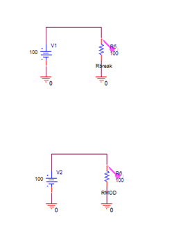
Figure 4: Circuit to understand Temperature Effects on Passive Components
Suppose that a resistor's resistance multiplier is unity when measured at 0οC. To signify this, T_MEASURED can be specified in the resistor's corresponding .MODEL statement as
.MODEL RMOD RES(R=1, TC1=0.0001, T_MEASURED=0)
When the circuit is operating at 0οC, R evaluates to 1. At 100οC, R evaluates to 1.01 which is the resistance multiplier (R=1) plus the first order operational temperature effect (TC1 * (TEMPT_ MEASURED)).
T_ABS allows specification of an absolute device temperature. If T_ABS is specified as T_ABS=25, the model is held at 25οC no matter what the circuit's operational temperature is doing. Adding T_ABS=25 to the model definition causes R to evaluate to 1.0025 at all times, even if the operational temperature is varied within parametric or DC sweep analyses.
T_REL_GLOBAL is used to specify a device temperature that is relative to the circuit's operational temperature. For example, a power resistor might be dissipating power and be warmer than its surrounding global ambient by 10οC. This can be specified in a .MODEL statement as
.MODEL Rbreak RES (R=1, TC1=0.001, T_REL_GLOBAL=10)
T_REL_LOCAL is used in the AKO ("a kind of") .MODEL statement. An AKO model references an existing model, thus inheriting the existing model's parameter definitions. Parameter values can be overridden or added by specifying them in the AKO .MODEL statement. Using this technique, the device temperature defined in a new model can be calculated relative to the absolute device temperature specified in a base model. The base model must define the absolute device temperature using the T_ABS parameter. The AKO model must define the relative change to the T_ABS temperature using the T_REL_LOCAL parameter.
For example, a model, RMOD, whose device temperature is 117οC greater than that specified in the RBASE model statement can be defined as
* Base Model
.MODEL RBASE RES(R=1, TC1=0.001, T_ABS=10)
* AKO Model
.MODEL RMOD AKO:RBASE RES(T_REL_LOCAL=117)
RBASE sets a resistor's absolute temperature to 10οC. RMOD evaluates to 127οC.
The PSpice simulation results of a circuit that has passive components with the .MODEL statements can be seen in Figure 5.
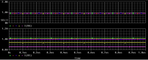
Figure 5: Simulation results of passive components with .MODEL statements
© Copyright 2016 Cadence Design Systems, Inc. All rights reserved. Cadence, the Cadence logo, and Spectre are registered trademarks of Cadence Design Systems, Inc. All others are properties of their respective holders.
Copyright © 2020 Cadence Design Systems, Inc. All rights reserved.