Here you will find out latest app notes.
This document explains how a Quartz Crystal can be modeled using a series RLC circuit and a parallel (package) Capacitor. Please note that Crystal Oscillators are available in the XTAL.OLB Library under the SPB/OrCAD Installation.
Crystal oscillators can be modeled as a series RLC circuit along with a parallel capacitor as shown in Figure 1. Quartz crystal oscillators tend to operate towards their “series resonance”.
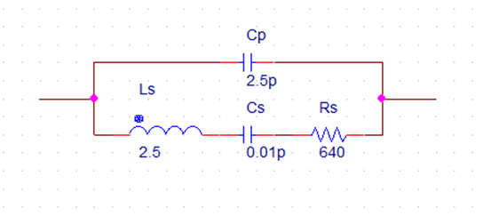
Figure 1: Equivalent Electrical Model
The equivalent impedance of the crystal has a series resonance where Cs resonates with inductance, Ls at the crystals operating frequency. This frequency is called the crystals series frequency, ƒs. As well as this series frequency, there is a second frequency point established as a result of the parallel resonance created when Ls and Cs resonates with the parallel capacitor Cp as described below:
Crystal Impedance against Frequency
R = R and XLS = 2πfLs
XCS=1/2πfCs and XCP = 1/2πfCp
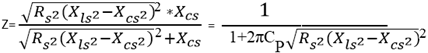
XS = R2+(XLS-XCS)2
XCP = 1/(2πfCp ) and XP = (Xs*XCP)/(Xs+XCP )
fs = 1/(2π√ Ls Cs )
fp = 1/2π√ Ls (Cp *Cs)/(Cp+Cs )
Q = XL/R = 2πfL/R
If this Q-factor value is high, it contributes to a greater frequency stability of the crystal at its operating frequency making it ideal to construct crystal oscillator circuits.
A Crystal has an extremely high Q-Factor (Quality Factor) of 5000 or more, which leads to very long simulation time for any oscillation to build up.
It is possible that due to numerical range initial amplitude build up may not get propagated to next simulation cycle and the oscillation build up is not visible.
A pulse is injected in the Crystal circuit or Initial Condition specified on Capacitors to accelerate the amplitude build up and speed up simulation.
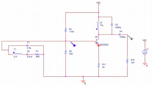
Figure 2: Circuit diagram
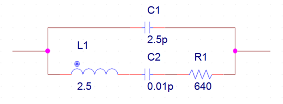
Figure 3: Equivalent Circuit (Model) Parameters
L1 = 2.5, C2 = 0.01pF, R1 = 640Ω, C1 = 2.5pF
Series Resonant Frequency
fs = 1/2π√ Ls Cs = 1/2π√ 2.5*0.01p = 1.0065MHz
Parallel Resonant Frequency
fp = 1/2π√ Ls (Cp *Cs)/(Cp+Cs ) = 1/2π√ 2.5(2.5p*0.01p)/(2.5p+0.01p) = 1.0085MHz
Crystal Oscillators Q-factor
Q = XL/R = 2πfL/R = (2π*106*2.5)/640 = 0.0245436*106 = 24543 ≈ 25000
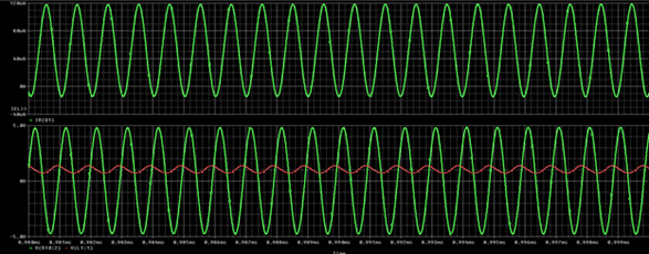
Figure 4: Simulation Results
© Copyright 2016 Cadence Design Systems, Inc. All rights reserved. Cadence, the Cadence logo, and Spectre are registered trademarks of Cadence Design Systems, Inc. All others are properties of their respective holders
Copyright © 2020 Cadence Design Systems, Inc. All rights reserved.