Here you will find out latest app notes.
The new inductor coupling symbols may be used to couple up to six independent inductors on a schematic. This application note covers the following topics explaining the use of inductor coupling symbols in a Capture PSpice project.
The magnetic.olb library contains magnetic core models for commonly available nonlinear transformer cores. The core symbols have no pins; they are represented by the letter K enclosed in a box. For example, E13_6_6_3C81 part in magnetic.olb, represents an E core of size 13/6/6 and material grade 3C81. When using parts from magnetic.olb, you need to specify the coupling coefficient and the reference designator values of the inductors to be coupled. The inductor values are specified as number of turns. For example, top-left circuit in Figure 1, simulates a 20 turn inductor ( L3) on P42 pot core material grade 3C85. This core is represented by P42_29_3C85 part instance and model. The core model is represented by symbol instance K2.Generation of photocurrent
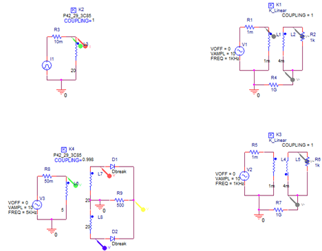
Figure 1: Examples of Inductive Coupling
To specify the parameters, double-click on a coupling symbol (on the K-in-a-box, not the attributes), and enter the reference designators for the coupled inductor as the values for Li (i=1,2,...,5). Set the value of the COUPLING attribute to the value of the coupling factor, K. In this circuit, the COUPLING value is set as 1.
The circuit describes the relationship between inductance, voltage, and current, that is
V=L(di/dt)
The curves in Figure 2 shows that as di/dt changes, the voltage changes.
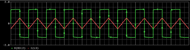
Figure 2: Inductor voltage and current
Besides the core library, magnetic.olb, you can also use the inductor coupling parts, Kbreak and K_linear, to represent transformer cores. The K_linear part from the analog.olb library, is used to represent a linear or an air core. When using K_linear part, you specify the coupling coffecient and the reference designator values of the tranformer windings (inductors) to be coupled. With K_linear cores, the inductances values of the tranformer windings must be specified in Henry (H). The Kbreak part from the breakout.olb library, is a generic symbol that can be used represent nonlinear cores. Kbreak has a pre-assigned model attribute, but its corresponding model in the breakout.lib library will not have a pre defined model parameters and it will simulate a core with default simulator model parameters. In this section, we will cover three example circuits that will help in understanding the usage of Kbreak and K_Linear symbols. These are the following:
Top-right circuit in Figure 1, represents a simple sine wave step-up transformer with step up ratio of 2. This step up ratio is define by (Ls/Lp)1/2 , where Ls is inductance of secondary coil and Lp is inductance of primary coil. In this case step up ratio is (L2/L1)1/2, which is (4m/1m)1/2 =2. Therefore, in figure 3, voltage of the secondary coil is 2 times of the voltage of the primary winding.
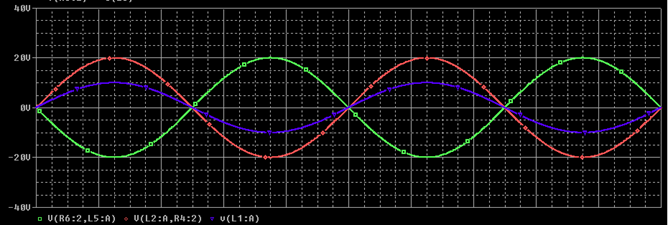
Figure 3: Simple two winding Transformer
Important: You will also notice that a 1G ohm resistance R4 is added in the circuit. This resistance is required in a simulation environment to provide reference and DC path to all nodes. In absence of this resistance, PSpice will give a floating point error. This high value resistance effectively keeps the secondary inductance floating and provides a DC path and a ground reference for the simulation.
The bottom-right circuit in Figure 1 simulates with the exact same transformer but with reverse dot convention from the one shown in Figure 2. In Figure 4, you will see that the output voltage of top-right circuit secondary's winding and bottom-right circuit's secondary winding are out of phase with each other for exact same input.
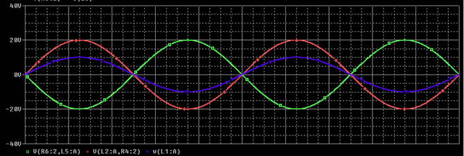
Figure 4: transformer with different dot convention
In Figure 1, the bottom-left circuit is a Center-tapped Full Wave Rectifier. It is an example of various multi-winding transformers with desired coupling.
Figure 5 shows the input and output voltage waveform of the Center-tapped Full Wave Rectifier circuit generated using a PSpice simulation.
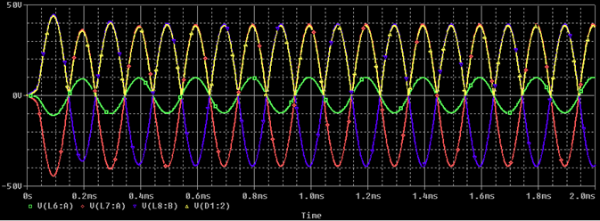
Figure 5: Center-tapped Full-Wave Rectifier Transformer
To define your own CORE model parameters, do the following steps:
© Copyright 2016 Cadence Design Systems, Inc. All rights reserved. Cadence, the Cadence logo, and Spectre are registered trademarks of Cadence Design Systems, Inc. All others are properties of their respective holders.
Copyright © 2020 Cadence Design Systems, Inc. All rights reserved.