Here you will find out latest app notes.
In this application note, let us model some Voltage Controlled Oscillators (VCOs), such as, Dual Integrator VCO and Controlled Reactance VCO, using PSpice. Most of the examples in the application note use the Analog Behavioral Modeling capabilities of PSpice. Most of the examples in the application note use the Analog Behavioral Modeling capabilities of PSpice.
An alternate approach to a behavioral model VCO is to start from a 2-integrator loop. Changing the time constant of one or both integrators allows the frequency of oscillation to be controlled. Some form of limiting is required in order to produce output of bounded amplitude.
A particularly elegant example can be found in Reference[1]. This sinusoidal VCO has independent control of both frequency and amplitude. It's black-box representation reduces to:
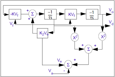
Figure 1: Black-box representation of a sinusoidal VCO
Outputs Vd and Vo are in quadrature. The amplitude error term is obtained by squaring and summing the quadrature outputs, and subtracting the amplitude-setting voltage Va.
Using the .FUNC command, the entire VCO can be reduced to two integrators with controlled current sources whose expressions incorporate the multiplications, additions, and subtractions.
Following is an example to model the above VCO:
* Filanovksy VCO
.func ve(x,y,z) k*(pwr(x,2)+pwr(y,2)-pwr(z,2)
.param k=0.1, cv=10u
g1 vd 0 value {k*((-v(vo)*v(vf))+(ve(v(vo),v(vd),v(va))*v(vd)))}
c1 vd 0 {cv}
r1 vd 0 1G
g2 vo 0 value {k*v(vd)*v(vf)}
c2 vo 0 {cv}
r2 vo 0 1G
.ic v(vd)=0.1, v(vo)=0
va va 0 1v
vf vf 0 1v
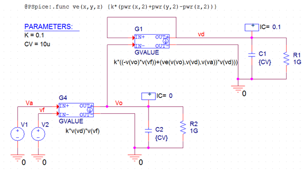
Figure 2: Circuit Design for Filanovsky VCO
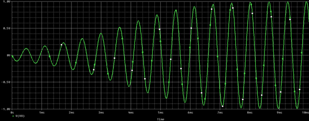
Figure 3: Simulation results for Filanovsky VCO
A more circuit oriented approach to build a VCO is to take a simple tank oscillator and use a voltage-dependent reactance for one of the tank components. The following example is a Colpitts oscillator. The zx device is used to implement a voltage-controlled lossy inductor.
xvi ctrl 0 ref vcc c zx;Colpitts with variable tank element,
lref ref ref1 15u
rref ref1 0 2.0
c1 c e 20n
c2 e 0 200n
q1 c 0 e q2n2222
re e vee 2k
vcc vcc 0 10v
vee vee 0 -10v
vctrl ctrl 0 pwl(0,1.5v 124u,1.5v 125u,2.5v)
.ic v(c) = 10 v(e) = -0.7
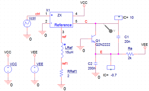
Figure 4: Circut Design for Controlled Reactance VCO
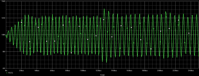
Figure 5 : Simulation results for Controlled Reactance VCO
Reference
[1] I. M. Filanovsky, “Sinusoidal VCO with Control of Frequency and Amplitude,” Proceedings of the 32nd Symposium on Circuits and Systems, IEEE, Vol I, 446-449 (1989).
© Copyright 2016 Cadence Design Systems, Inc. All rights reserved. Cadence, the Cadence logo, and Spectre are registered trademarks of Cadence Design Systems, Inc. All others are properties of their respective holders.
Copyright © 2020 Cadence Design Systems, Inc. All rights reserved.