
Hello,
I need to simulate a DC current transformer in Pspice. In the internet I found this model. (I edited the values of the components because I need an output of 4 Volt at a current of 100 A):
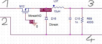
In the pdf-document of the circuit, which I have to simulate, the current transformer looks like this:

Which pin (1 to 4) corresponds to which pin in the picture below?
Are there pins that aren't connected in the picture above?
Or is this model of the DC current transformer already false?
Thank you in advance.
Kind regards
Julian
Copyright © 2020 Cadence Design Systems, Inc. All rights reserved.
Simplest way for this to use H device - which is Current Controlled Voltage Source. This will act like an ideal current transformer and work with any waveshape including DC. Refer PSpice reference guide - Controlled sources section for details. You can find this device by using PSpice search or look for "H" in Analog library.
How can I use the H device?
Are the pins on the right side of the picture below in my origin comment equal to the pins with the arrow of the H device?
Which pins are equal to the other two pins of the H device?
And where do I find the Pspice Model of this device?
Thank you in advance.
Hi,
Below is an example schematic on how to use an H device. It takes current as input and gives voltage as output based on the input current and the gain set for the device. It works as an ideal current transformer. This is an alternative solution to the device U1 you wish to use. The ouput you require (4V output for an input current of 100A) can be easily achieved with H device by setting its gain. You can find "H" in analog library as shown in right side of the image below.
Hello,
thank you very much for your help.
Do you know a source, which tells me, that I can simulate a current transformer by using a current controlled voltage source?
To simulate a DC current transformer, you can model it as a two-winding transformer, where one winding carries the primary current and the other winding fnf produces the output voltage. The turn ratio of the transformer determines the output voltage, and you can adjust this ratio to achieve your desired output voltage at a given current.
A primary winding (input) and a secondary winding (output) make up a DC current transformer. The primary winding and the current being measured are connected in series, and the secondary winding produces an output corresponding to the primary winding's current
My Singing Monsters
I really like the information you share. Thanks to that, I know many more interesting and useful things. directions
A DC current transformer is made up of two windings: an input (primary winding) and an output (secondary winding). The secondary winding generates an output equal to the io games current flowing through the primary winding when the primary winding and the current being measured are coupled in series.
DC Current Transformers (DCCTs) have been used for suika game pc decades as non-intercepting standard equipment for measuring online beam current in synchrotrons and storage rings.
I don't think this DC current transformer model is wrong, maybe there are some other factors
slope that influence the results.
The model you provided is a possible configuration for simulating a DC transformer in PSpice. However, it is important to note that the accuracy of the simulation will depend on the specific characteristics of the current transformer you are trying to model
slice master and the values of the components used in the circuit.