
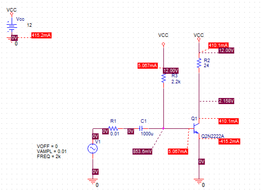
I have designed a very simple CE amplifer. At the first look everythings is ok but there are some issues that I can not understand.
1. As we know and also PSpice ref. guide said Ic = Is exp(Vbe/Vt) which for 2n2222 Is=14.34f and Vt=25.8mV and Vbe=853.6mV so Ic=3.35A which is too far from 410mA!!!!!
2. DC beta here is near 80 but AC beta is near 50.
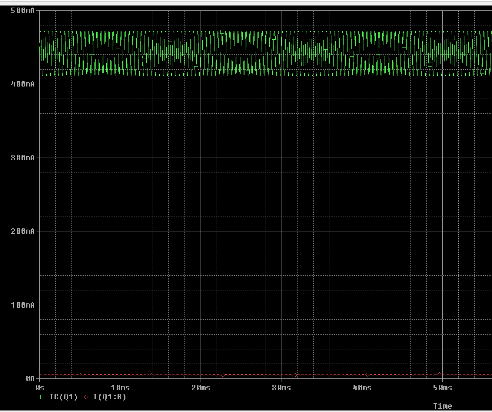
3. Why none of gm (hybrid pi model) relation did not works? for example gm=Ic/Vt so gm=(410e-3)/(25.8e-3)=15.8, so iC=gm*Vb=15.8*0.01=158mA which is near 4 times of simulated value of 40mA.
4. As 2n2222 datasheet shows Is=14.34f but in modeleditor Is=166.78e-15. why?
Copyright © 2020 Cadence Design Systems, Inc. All rights reserved.
I'm not sure device remains linear at this base bias current. Seems a little high. You may want to look into that, might be in early stages of compression. R2 won't let collector current get above 500mA anyway so there's that. You may want to reconfig to a CER architecture, you might be able to get to your goal then. Or...back off on base bias to more linear region.