
Hello,
I'm a beginner with PSpice and for may application I need to simulate a converter DC/DC. After finding the circuit and calculating the values normally I must have -5V at 0.7A output from this component but nothing works.
Do you have any idea where my mistakes come from ? Thank you for your helps
Regards
Copyright © 2020 Cadence Design Systems, Inc. All rights reserved.
Hi,
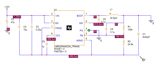
We ahve analyzed the circuit and it looks fine. Only Mistake I could figure out is the value of output capacitor C7 ( as seems from snapshot).
If you want value to be 88uF, then simply put it as 88uF. Here 4x22uF expression is not denoting multiplication and hence wrong results.
Change it to 88uF and you will see -5V output voltage.
Also you can take reference from LMR33640ADDA_TRANS reference design available in Pspcie for TI.
Regards
Ashish Gupta
Hi,
Thank you for your answer, about the capacitor I think that means 4 capacitor for the value 22uF in in parallel. Where you see I can take reference from LMR33640ADDA_TRANS reference design available in Pspcie for TI ? Can you show me the way to open this file Please ?
Thank you
Yann DO
Hi,
After searching a bit finally I found the simulation model. I have this windows
Now I'll see how it works.
Hi, you can try tiny fishing to solve the problem
Can nicely write on similar topics! Welcome to here you'll find out how it should look. 카지노사이트
Many readers around the globe want to read every day and I feel like you are one of the only people who delivers that. Your work is good 6 out of 7 days and that's just absurd for any writer. Continue doing your work. 여우알바
Once again, the article shared here is amazing. There's hardly been any bad articles on this site. This site is definitely better than, where most of the articles have bad formatting. I will visit this site every day now. 인터넷카지노
Great! Thanks for your answer. This is what I am looking for. I appreciate it and uno online which is awesome.