
Hi all,
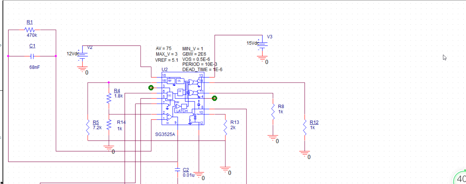
I simulated a PWM output with SG3525A model, but i meet an issue that the PWM's frequency is controlled by the period of parts proterty, but not by Ct, RT and RD (pin 5,6,7). that means no matter how to adjust the values CT, RT or RD, the PWM's frequency doesn't change. So could someone please tell me how can i adjust the frequency of PWM via Ct, RT and RD (pin 5,6,7), but not with the period value in the parts proterty ? of cause, in orcad capture Pspice.
Thanks very much in advance! :)
Copyright © 2020 Cadence Design Systems, Inc. All rights reserved.
I truly value this superb post that you have accommodated us. I guarantee this would be helpful for a large portion of the general population. Time postings
The location of the circuits you share is clear and detailed. Actually, for the physics related to this technique, if you don't understand the principles, it will be difficult to know the exact location. I follow and update diverse knowledge. It's fascinating to follow geometry dash lite