
Hello,
I constructed the buck converter shown below. As i saw, in most buck converter schematics the pulse generator is connected like i did (positive side on the transistor gate and negative on the drain). My problem is that when i measure the gate voltage is a pulse of approximately 10Volts isntead of the 5Volts i gave to V2 (of the pulse generator) Furthermore, if i would like to construct it to a pcb and connect a pwm (pulse width modulation) signal from a microcontroller (instead of pulse generator of PSpice) how will this connection be done?
Thank you.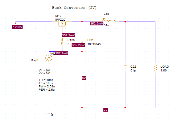
Copyright © 2020 Cadence Design Systems, Inc. All rights reserved.
Hi John,
The thing is for this buck converter supply to work proberly M18 should turn ON and OFF properly.
IRFZ20 ( M18) is N-Ch Enhancement type MOSFET and turning ON of this MOSFET requires Vgs>Vth and Vth for IRFZ20= 4V(max).
So Vgs>4V, Pulse that we are providing at Gate terminal should give a voltage of greater than 4V with respect to Source terminal. Hence in simulation we connect other end of Pulse to Source terminal of MOSFET (as hown in your circuit) so that Vgs is directly given at gate terminal.
Hence as per your circuit measuring gate voltage ( with repect to ground) will give more voltage than pulse applied since voltage at source terminal wil add up in measurement..
In PCB world if you wish to giv PWM pulse through microcontroller then you can do that, just ensure that the level of controller pulse should be such that MOSFET turn ON condition should be met as described above. Snapshot of such circuit is shown below. Here if you measure Vgs with differential probe then pulses of nearly 5V amplitude will be there which will turn ON the M3 easily.
Hope it helps
Regards
Ashish Gupta
Thank you for your help. If i connect negative side of pulse generator at ground (so as to simulate microcontroller) instead of transistor source my circuit doesn't operate correctly ,maybe because the Vgs is not over 4V so as the MOSFET to be turned on. How could i change my schematic to make it to operate normally?