Here you will find out latest app notes.
The standard simulation methodology to test for settling time of an amplifier is to step the input voltage over the relevant input range and measure the time taken for the output to settle to some defined value close to its steady state value. The defined value depends upon the resolution of the system. For example, a 12 bit system in a range of ten volts will probably need to settle to within 1.2 mV (1/2 lsb) of its final value. During the design of such an amplifier, many parameters are varied to optimize the settling time. It can become extremely tedious moving along the response curves to find the exact settling time. Performance Analysis by means of goal function definition, can facilitate this investigation. In this application note, the settling time of an LF411 in unity gain configuration will be computed as a function of load capacitance by implementing relevant goal functions.
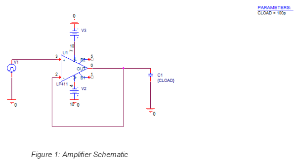
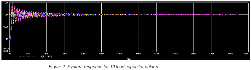
Figure 2 shows the response of the system for 10 different load capacitors, to a one volt step at the input.The method normally used to estimate the settling time from these curves is fairly straightforward. We simply start at the end point and scan backwards along the curve until we find a point where the response curve intersects the defined settled value
The following goal function demonstrates the backwards search from the end of the run to where the defined value (1.01 volts in this case) intersects the curve.
settle(1) = x1
{
1|
search
backward/End/level(1.01) !1
;
The goal functions to implement this are shown below as S1, S2, and S3, which are three components of the Lagrangian polynomial. In the example shown, the Lagrangian components are evaluated at a defined level of 1.01, which, when added together, will produce the settling time curve to 10 mV.
S1(1) = (1.01-y2)*(1.01-y3)*x1/((y1-y2)*(y1-y3))
{
1|Search backward /end/ LEVEL(1.01)
Search forward peak !1
Search backward peak !2
Search backward peak !3;
}
S2(1) = (1.01-y1)*(1.01-y3)*x2/((y2-y1)*(y2-y3))
{
1|Search backward /end/ LEVEL(1.01)
Search forward peak !1
Search backward peak !2
Search backward peak !3;
}
S3(1) = (1.01-y1)*(1.01-y2)*x3/((y3-y1)*(y3-y2))
{
1|Search backward /end/ LEVEL(1.01)
Search forward peak !1
Search backward peak !2
Search backward peak !3;
}
S105(1) = (1.005-y2)*(1.005-y3)*x1/((y1-y2)*(y1-y3))
{
1|Search backward /end/ LEVEL(1.005)
Search forward peak !1
Search backward peak !2
Search backward peak !3;
}
S205(1) = (1.005-y1)*(1.005-y3)*x2/((y2-y1)*(y2-y3))
{
1|Search backward /end/ LEVEL(1.005)
Search forward peak !1
Search backward peak !2
Search backward peak !3;
}
S305(1) = (1.005-y1)*(1.005-y2)*x3/((y3-y1)*(y3-y2))
{
1|Search backward /end/ LEVEL(1.005)
Search forward peak !1
Search backward peak !2
Search backward peak !3;
}
S120(1) = (1.02-y2)*(1.02-y3)*x1/((y1-y2)*(y1-y3))
{
1|Search backward /end/ LEVEL(1.02)
Search forward peak !1
Search backward peak !2
Search backward peak !3;
}
S220(1) = (1.02-y1)*(1.02-y3)*x2/((y2-y1)*(y2-y3))
{
1|Search backward /end/ LEVEL(1.02)
Search forward peak !1
Search backward peak !2
Search backward peak !3;
}
S320(1) = (1.02-y1)*(1.02-y2)*x3/((y3-y1)*(y3-y2))
{
1|Search backward /end/ LEVEL(1.02)
Search forward peak !1
Search backward peak !2
Search backward peak !3;
}
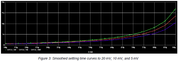
Different settling time curves can be produced by modifying the goal functions for different defined levels. Figure 3 shows the curves for the settling time to 20 mV, 10 mV, and 5 mV, by setting the defined level at 1.02, 1.01, and 1.005, respectively. Note that both the marked point expression and the LEVEL function are modified for each distinct defined level. In Figure 3, each settling time curve has been defined as a macro expression. For instance:
settle_10mV = s1(v(2)) + s2(v(2)) + s3(v(2))
To smooth the curves even further, a more appropriate function could be defined using goal functions.
© Copyright 2015 Cadence Design Systems, Inc. All rights reserved. Cadence, the Cadence logo, and Spectre are registered trademarks of Cadence Design Systems, Inc. All others are properties of their respective holders.
1766 12/13 CY/DM/PDF
Copyright © 2024 Cadence Design Systems, Inc. All rights reserved.