Here you will find out latest app notes.
This document explains how the model parameters IS and N can be modified to set the forward voltage drop of a Schottky diode. Attached test case shows the simulation results of varying these parameters.
Introduction
This document explains how the model parameters IS and N can be modified to set the forward voltage drop of a Schottky diode. Attached test case shows the simulation results of varying these parameters. The project has three simulation profiles;
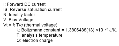
1. dc: DC sweep analysis of forward biased schottky diode as shown in Fig. 2.
2. IS_Variation: Nested DC sweep. Shows effect of IS variation.
3. N_Variation: Nested DC sweep. Shows effect of N variation.
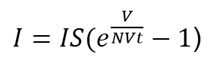 (1)
(1)
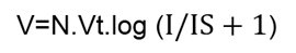 (2)
(2)
Where
With respect to the above diode equation, we can see that the forward voltage drop, V, depends on the current, I, but only weakly. V increases by 60 millivolts for each factor of 10 that I increases. Alternatively, V increases by 60 millivolts for each factor of 10 that IS decreases. So, the forward voltage drop for your circuit’s bias conditions can be set by changing IS parameter. You can change this in the diode’s .MODEL statement. For Schottky diodes, values of IS are larger when compared to diffusion diodes of the same area. The model parameter N can also be used to adjust the forward voltage drop, but changing N will make the I-V curve deviate from the normal slope of a decade per 60 millivolts. We do not recommend changing N in order to model Schottky diodes. The attached test case shows the effect with DC sweep of IS and N parameters.
Fig. 1 and 2 show the circuit and the model being used for this simulation.
Figure 1: Circuit diagram in Allegro Design Entry CIS (Capture CIS)
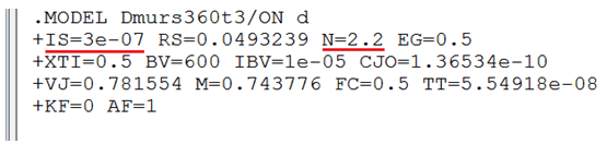
Figure 2: PSpice Model parameters
Do a DC sweep of above circuit, sweeping V1 linearly from 0.1 to 3.5 with an increment of 0.001. Fig. 3 shows the simulation results. Value of IS is 3e-07 and N is 2.2.
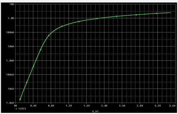
Figure 3: Simulation results - IS=3e-07, N=2.2
DC nested sweep is done to vary the Model parameter 'IS'. Secondary sweep is done for IS values of 3e-04, 3e-06 and 3e-08. Simulate profile ‘IS_variation’ in attached test case.
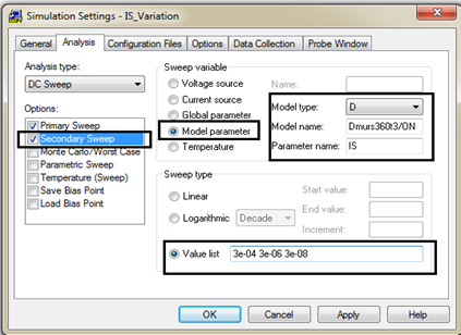
Figure 4: Simulation setting for DC nested sweep - varying model parameter IS
Fig. 5 shows the effect of varying IS parameter. You can see that as IS decreases, for the same Forward Current (I) we get greater Forward bias Voltage (V).
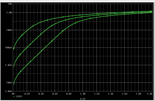
Figure 5: Effect of varying IS parameter value for a Schottky diode
DC nested sweep is done to vary the Model parameter 'N'. Secondary sweep is done for N values of 2.2, 2.4, 2.6, 2.8 and 3. Simulate profile ‘N_variation’ in attached test case.
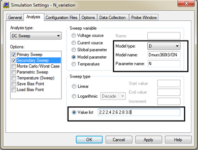
Figure 4A: Simulation setting for DC nested sweep- varying model parameter N
Fig. 7 shows the effect of varying N parameter. You can see that slope of the forward current changes with changing N.
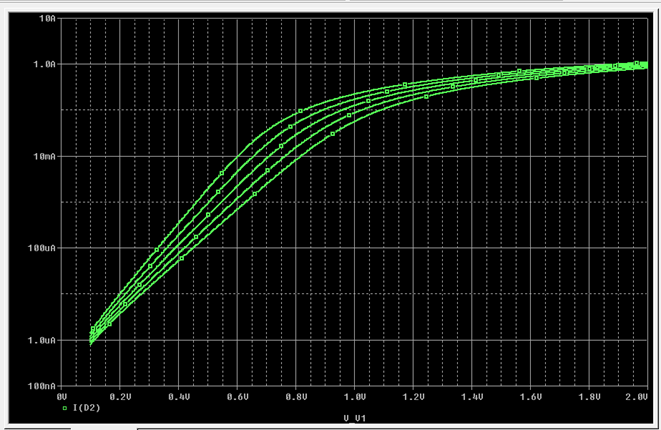
Figure 7: Effect of varying N parameter value for a Schottky diode
[1] D. A. Hodges and H. G. Jackson, Analysis and Design of Digital Integrated Circuits, McGraw-Hill.
© Copyright 2016 Cadence Design Systems, Inc. All rights reserved. Cadence, the Cadence logo, and Spectre are registered trademarks of Cadence Design Systems, Inc. All others are properties of their respective holders.
Copyright © 2024 Cadence Design Systems, Inc. All rights reserved.